Time-of-flight measurement
2010/08/28One of the requirements of the product I’m developing is that I be able to tell the relative distance along a wire of all the nodes in the network. Because they are sitting on the bus in parallel and are not allowed to cut and internally bridge the wire, I have to use some arcane methods to figure out where they all are.
What I found was a chip from ACAM called the GP2, which is a time-of-flight measurement chip capable of 50 picosecond resolution measurements between start and stop pulses. Using this, I can tell each node in turn to place a short across the bus (held with power from a cap), and measure how long it takes for a pulse to traverse one half of the wire, the node, and the other half. By making averaged measurements and sorting the nodes, I can determine their order on the bus.
The first generation board for this included a bunch of jumpers to allow me to reconfigure the various timing-side pins:
It took quite a bit of time to work out how to get the chip to function in the first place, thus the extra resistor and jumper wire around the crystal. Turns out ACAM put a pretty fragile oscillator on their chips, which requires both a drive-side series resistor (220R) and as well as a parallel resistor (560K) in order to work. This could be contrasted with a conventional 8-bit microcontroller that generally functions without anything except the crystal at all, but is “cleaner” with load caps. Sigh.
The jumpers allow me to enable the start and stop inputs, route the fire-pulse generator to start and the line interfaces, gang the two generators together (for 96mA drive current), and configure the “fire-around” mechanism that I don’t entirely understand since I don’t need it…
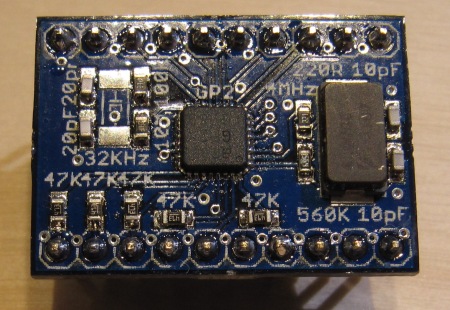
In an effort to make the design more useful for integration into a protoboard form of the network master, I redesigned it as a 600mil DIP module:
All the same functionality is present, but without all the jumpers. The 32KHz calibration crystal is missing from this board because Digi-Key had (and still does, my notification to them apparently not having taken effect yet) the ECS-.327-7-38-TR listed as a 4.9×1.8mm crystal, rather than the 7.0×1.5mm it really is… I have actual 4.9×1.8mm crystals coming on Monday or Tuesday, so I’ll fill that in. However, since I don’t actually care about absolute accuracy at this point, I really could care less about the calibration clock. On the bottom is a (unpopulated) site for an MCP1703-3.3 regulator, with pins on the top left for both +5V and +3V3. All the power and digital I/O is on the top side, while all the measurement-side pins are on the bottom.
Getting the chip actually running was a monumental exercise in frustration, since the datasheet (“registration” required) for the chip is easily the worst-laid-out document of its type I’ve ever run across. While the designers of the time-of-flight core in the chip were clearly rather talented, whoever did the SPI and registers front-end needs to be shot. Repeatedly. That being said, I plan on writing up a better organized and more coherent “quick start” along with default registers for the module… I’ll probably even publish (as-is) the Python GUI I created to tweak all the registers more easily, which operates via BusPirate.
The first board pictured is about to be shipped to a guy in Brazil who managed to find my un-set-up webshop with it listed. At some point soon I need to try rebuilding the shop with a different backend and actually get it up and running fully, at which point I’ll be offering the DIP module for sale. Lead time on the module will be somewhat long though, since the one pictured above has the last of the 3 chips I purchased at ~$32 each. If anybody wants one, I’ll have to order more chips first. I have 2 unpopulated boards in my possession at the moment, so if you’re interested in one, speak up ;-)


This sounds interesting. Do you know of a similar solution for wireless nodes? Resolution of about 1ns is acceptable.
Thanks
It depends on what kind of wireless you’re talking about. If you mean free-space optical, then this chip could do the job with an appropriate front-end between it and the optical receiver. If you have an RF system, you’d have to have something that can receive a trigger signal and return a response with a highly consistent set of timings. That’s unlikely to be realistic at 1ns.
Fundamentally, this particular chip will give you timing difference between any start and stop pulse within a certain timespan. How you get that start pulse there and back is up to your own application.
hello
I don’t know if you still visit your blog but how can I get my hands on one of your boards using acam TDC?
Or could you share the schematics and the components used for this board? I am willing to pay.