h1

Cheap eBay reflow oven

2013/04/25

I recently got a T-962 reflow oven from one of the many front-ends for the same fulfillment shop in California that sells various Chinese imports.  The unit cost $240 with free shipping, and arrived in roughly a week.  It’s the smaller of the two available units, the B model having a 1000W element rather than 800W, and a somewhat larger overall work space.  The unit came shipped in the usual Chinese style: wrap the unit in enough bubblewrap to fill the box on its own, stuff into cardboard box, then add about as much tape by weight (waterpoofing?).  The build quality is reasonable enough at first glance.

I started out with a few small boards (my Xmega DIP adapters) and went with “wave 2” designed for 63Sn/37Pb, peak temp of 225C.  Right off we have our first problem: the UI is horrible.  The screen itself is fine, but the font used is nasty.  The buttons are OK physically, but they’re only scanned once per second(!), which means you have to hold them down until it decides to notice.  Unfortunately, it doesn’t do any state latching, so if you hold it down a little too long, it’ll treat it like another button press.  Apparently debounce and interrupts are too complicated.  Even worse, when exiting some menus, it immediately processes that button press again.  A prime example is anything that uses F4 to return to the main menu: main F4 means “switch languages”….

The next problem is that while there’s a “cool-down” fan in the back, some genius decided that it should blow in to the chassis.  This results in all the solder fumes being pushed out the open bottom of the oven, and into your local atmosphere.  My absolute first modification to the oven will be turning that fan around.  I then need to find a flange with screw mounts for a 4″ flex-duct, at which point I can route the exhaust into my theoretical wall vent and continue breathing actual oxygen.

As you might expect, I took the unit apart to figure out what all is inside.  The answer: an insane amount of very tenacious hot-glue.  They hot-glued everything.  I spent a chunk of time removing all the hot-glue, because it was unnecessary (now that it’s shipped to me…) and because I wanted to actually be able to disassemble it.  I didn’t take any pictures the first time I took it apart, I’ll have to do so again and get all the detail I need.  Unfortunately the fan that needs to be reversed is buried inside several more layers of insulation and silver (duct) tape.  I didn’t dig that far into it yet because I actually need to make certain it’s usable for a while still…

The main board is designed to be split, with the various power stages on one side and the logic on the other.  The MCU is an LPC2134 (ish), with a funky programming header (1×6?) nearby, which bodes well for fixing the firmware stupidities.  A full reverse-engineering of the board will be necessary to figure out all the I/Os, but it doesn’t look like it’ll be a huge challenge.  The good news is that everything looks to be easily controllable, so enhancing the functionality with new firmware should be easy enough.

Just now I did a “large” panel of PCBs, taking up most of the available working space.  Here we find another issue with the oven: it’s not very even.  The panel had a 4×4 grid of boards, and the front row didn’t really come close to soldering in the preprogrammed “wave2”.  I had to not only switch to manual and keep the peak temperature in place for quite a while, but I had to open the tray and very carefully rotate the entire panel 180deg in order to put the unsoldered boards in a hotspot.

New firmware could fix this by running the “cooldown” fan at a very low speed during heating cycles.  The bottom of the unit might need to be taped up in order to force incoming air to enter from the front of the chassis and pull across the boards, though I haven’t looked at the bottom much.  The other advantage of doing this is that the “preheat” stage where the flux fumes start to off-gas would be exhausted to the outside.

At some point when free time actually exists, I’m hoping to hack up new firmware (after swapping out the chip if it’s code-locked, so I don’t kill it completely) and make it a bit more viable.

h1

Crazy-accurate PCB stencils via Silhouette Cameo

2013/04/05

Wow, I haven’t posted anything here in way too long.  This might help.

Right now I’m working on getting accurate PCB stencils out of my Silhouette Cameo desktop cutter.  People have been doing this for a while now, but they’ve been plagued by various complications with the data workflow and physical cutter settings.  The process involved transforming your artwork through several formats, importing into a proprietary application (you can buy SVG support for $50…), and hoping you have everything set right.

My initial work on the process was to change the data flow, allowing me to work from Gerbers rather than exporting a different format from Eagle.  It was a cumbersome process that involved using gerbv to write SVG files, then loading those into Inkscape in order to save them out as “R14” DXF, then switching over to my Windows VM to import the file into Silhouette Studio, dragging it to the right spot, and then cutting.  This at least allowed me the possibility of cutting an entire panel as generated by gerbmerge, but took waaay too long.

Now, I’m well on my way to having a radically superior process in place.  First off, I found that there are several projects capable of talking to the Graphtec engine that the Cameo is based on.  These gave me the foundation to write my own simple code to control the cutter, although there are still a lot of “magic commands” that need to be figured out the hard way (I’ll have to set up USB sniffing and exercise Studio a fair bit to figure them out, if I care).  That got me a Python script that could cut whatever I wanted programmatically.

The next step was to try to clean up the physical results.  Ever since I started cutting stencils, I’ve been plagued with strange shapes instead of nice rectilinear openings.  Well, this turns out to be a function of the design of the Cameo blade.  Inside the cutter is a vertical shaft with a very small triangular knife blade that spins freely.  The shaft is centered on the nominal X,Y of the cutter head, but the tip of the blade is not.  It drags roughly 0.5mm behind the center of the shaft.

This means that when you make a hard corner with the cutter head, the blade will not make the same corner.  As the center of the head (black) makes the sharp corner, the knife (red) lags behind and eventually ends up where the head wants it.  The result is a shape that roughly approximates the original, but only mostly.  Even worse, because the blade never actually reaches the start point, it leaves a little un-cut corner.

Cameo drag cutter     Not square!

My initial thought was to basically over-shoot the corner, then come back to the target line.  A simple method uses a single angled return path, but really it should be an arc of the same radius as the blade lag.

Initial compensation attempt

That mostly worked, but then I ran into another problem with blade-dragging: the blade drops with whatever rotation it had for its previous cut.

Drop misalign

In this case you can see that the blade was aligned from a previous upward cut when it dropped, then slowly made its way towards the right cut it was supposed to make.  The solution I came up with was to do a “pre-cut” off to the side before any lines of a given angle.  This leaves the blade pre-set at the right angle to make sure the beginning of the cut is straight.

The final trick was to cut each line in half, and actually force the blade to make two cuts starting from the center towards each end.  This avoids any question of exactly where the blade drops at the corners, and leaves and overshoot at every corner.  At least for rectilinear openings (all I care about just for now), this results in a perfect opening:

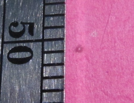
The Fifth Millimeter

That’s a millimeter ruler up against an 0.2mm square hole.  Not only is it nearly perfect (to the limit of my ability to actually see the thing!), but it lifted clear of the adhesive cutting mat exactly as you see: the fragment was 100% detached from the sheet.

At this point I’ve got a minimal codebase that reads actual stencil data, albeit the long way around: gerber -> gerbv -> Postscript -> pstoedit -> .pic(troff) -> myscript.  I’m hoping to fix that in the long run by reading Gerbers directly.

I have all sorts of transform functions in place to allow me to implement these techniques then send the resulting cut paths to the hardware.  I’m still tweaking a few things (I don’t have the cut-from-center trick written yet, but I do have a “repeat last line” to make 5 cuts around a rectangle) and getting period odd results (my last test left every single fragment still attached well enough to peel off with the main sheet…), but it won’t be long before I can take a Gerber file straight from Eagle CAM and generate a nearly perfect stencil on my $300 cutter!

h1

New scope!

2011/08/31

Today I got my new (rented) scope in the mail.  It’s an Agilent MSOX3014A with RS232 option.  It’s got 4 analog and 16 digital channels, with a 4Gsps capture rate and 100Mhz bandwidth (no need to spend up to twice as much for the max 500MHz unit, which is nothing more than a license upgrade anyway…).

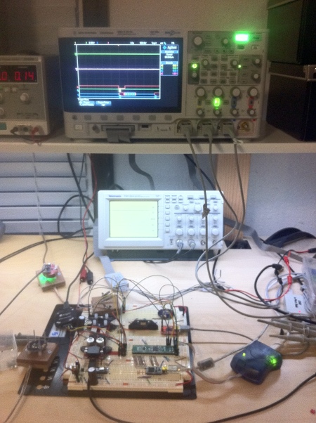
(sorry for the grainy iPhone image…)

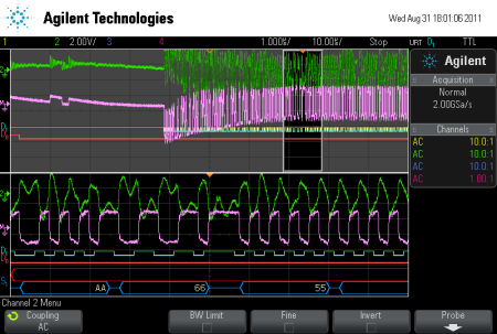
Here you can see the new scope, my old scope, and the project under development with some of the probes hooked up.  Here’s a shot of the scope in action, screenshot from it directly to a USB flash key:

This shot shows a lot of the features I that made me get this scope.  In this shot the screen is split into zoom mode, with 10us/div on top and 1us/div on bottom.  I can change the scale on the bottom and scroll it within the larger region at will, and it’s got all the data there at full resolution (2GS/s as shown).  The green trace is half of the RS-485 bus, while the pink trace is the math channel showing the differential result of that and its mate, after almost 100ft of lamp cord ;-)  D1 (cyan) and D0 (red) are the digital inputs hooked to the digital side of the bus controller.  S1 shows the RS-232 decode of that bus.  The really neat trick is that I’m actually triggering on the serial data, specifically 0x66.  You can see the orange triangle at the top of the two windows lining up with the end of the byte.  Since 0x66 happens to be the trigger byte for the end of the packet preamble in my design, what you see is preamble to the left and actual data to the right

I’ve even got the trigger output of this scope hooked up to a channel on my older TDS224, which allows the exact same waveform timings to be shown on the other scope at the same time ;-)

The scope also has a high-speed USB interface, which will allow me to set up, capture, and retrieve data from a Python script on my computer.  Since I have code already in place that will take a byte-stream in CSV format (so far from the Salaea Logic analyzer dump), it should be almost trivial for me to take the info from this scope and produce a human-readable packet dump.  The question is whether I can actually trigger and transfer data fast enough for every frame.  I suspect not, but that’s what the digital channels are good for: use a spare trace I/O on the board to signal a timeout or other bus condition, and go from there.

Only problem so far is that the thing’s got a decent-sized fan, which means both noise and heat ;-(

h1

My magic AVR build script

2011/08/11

Don’t get me wrong, I like make…  Hah! Yeah, right!

make has its place, no doubt, but small microcontroller projects not so much.  In my projects I like to just start coding, pulling in existing code where it makes sense.  Maintaining a makefile for that gets old really fast, and is massively overwrought compared to the requirements.

So, over the last couple years I’ve developed my own scripts to build AVR projects.  The latest variation has just received a major speedup, so I thought I’d share it along with some selected Bash tips.

Read the rest of this entry »

h1

New monitor and more OctoPDI5 boards

2011/07/15

Today a new monitor arrived for work, a 1920×1080 pivot-able LCD.  I’ll hold all the debug consoles for stations I’m building as I  scale out to as many as I can before the bus starts to fail (hopefully quite a ways).  I also built up more OctoPDI5 boards a couple days ago, so I now have 24 ports of fully-isolated program & debug.

I’ve actually managed to cram all 24 debug windows onto the screen at the same time.  Time will tell if they’re actually too small…  So far I’ve got 4 stations and the port controller hooked up, though I need to see if I can get a single-port PDI5 controller built to isolate the port controller.  For some reason when I have too many stations attached to the same OctoPDI5 as the port, engaging the power-cut relay on the controller causes enough noise that the controller resets and turns everything back on again…

h1

Absolutely ridiculous packaging from Arrow

2011/07/13

I order parts from various places, though mostly Digikey.  Sometimes parts are only available from certain distributors, or in some cases they can be noticeably cheaper even after counting in shipping to get parts from multiple distributors.  In this case one particular part I need qty.16 of was $7.48 from Arrow and $11.13 from Digikey, while another I needed qty.2 of was $7.17 vs $10.20.  The parts are 100-TQFP and 16-SOIC-W, so.. not very big.

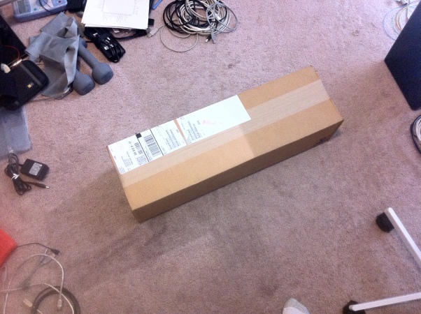
Imagine my surprise when UPS shows up with a 7″ x 8″ x 27″ box:

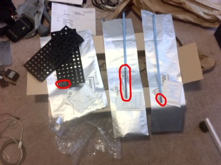
Inside this monstrous box there are 3 (!) large static bags, 7″ x28″ and 11″ x 18″.  One of them is covered in bubble-wrap, and all 3 of them are packed inside a large volume of loose paper.  Unpacking all 3 of these bags yields a full tray with 2 parts in it (the TQFP), a tube with 14 of the SOICs, and a second tube with 2 more of the SOICs (besides the large dessicant bag and moisture card in each):

Now, under absolutely no circumstances is this even remotely acceptable.  The SOIC parts should have been consolidated into a single tube, or at least they might have shortened the tube rather than cut additional plastic strips to fill the immense amount of empty space in them.  Even with 2 tubes they should have been packed in a single (smaller) bag.  The tray designed to hold 67 parts should have been chopped down significantly and packed in a smaller bag.  The entirety of this should have been in a radically smaller box, with less waste material.

In theory I saved $64.46 on the components by ordering them from Arrow rather than Digikey.  However, the shipping cost from Arrow was $14.99, reducing the cost savings to $49.47.  Saving $50 is a pretty good deal, but if the savings were any smaller, I would refuse to order anything from Arrow until they fix these absurd shipping practices.  The larger cost is in garbage, recycling, shipping volume and the resulting additional fuel cost for more trucks on the road with the additional traffic and noise.  You might say that this one package is a drop in the bucket, but unless I’m presented with evidence that Arrow only ships things like this to me (repeatedly, I might add), the impact is far larger than it might seem on the surface.

Responsible packing and shipping has been the watchword for years now, and Arrow needs to get a clue.

h1

Teensy-based PDI5 programmer

2011/07/12

I’m preparing to radically scale out my product development, which means a number of things.  First, I’ve ordered parts to populate 2 more of the “OctoPDI5” boards, so I can scale out to a total of 24 units under development at the same time, all of them electrically isolated from each other and the host computer.  I’ve also got an inexpensive 1920×1080 monitor on the way that will have enough room for me to actually put 24 copies of by debugging console on it in pivot mode.  However, I’ve still got to program/debug the controller board for this whole mess.  So far I haven’t had enough stations active at the same time to make me hit the 8-port limit on the OctoPDI5.  However, with 24 stations and 3 OctoPDI5’s, I’m going to need another programmer…

Luckily I have a Teensy++ sitting on my desk, which I haven’t had a chance to do much with yet besides play with the loader and core examples.  It’s nominally got all the stuff I need to pull this off, though before I actually connect it to anything I’ll need to alter it to run on 3.3V lest it blow out my port controller with 5V…

The software stack porting turns out to be quite trivial, because of the way I’ve set up all the code for the existing PDI5-related boards.  Basically I’ve built a rough object-oriented system for the various “streams” such as USARTs and the STK500V2 engine.  A little bit of hacking gave me both an “avrmega” standard USART module (though it’s hard-coded for USART1 so far; I’ll need to enhance it to run on “any” AVR mega, especially the one with more than one…) and a “USART” that uses PJRC’s usb_serial code.  A little more code gives me the “iosmux” mainloop that multiplexes the serial and stk500v2 streams through the upstream.  Some quick tweaks to my host-side software so it handles the /dev/ttyACM0 path instead of /dev/ttyUSB0, and I’ve got the basic ability to send a text substream out to hardware.

The next step will be porting the PDI physical layer to the “avrmega” type, and shuffling the pdi5 code around so it’s not hardcoded to the Xmega PHY.  Neither of those will be particularly difficult.  At that point I’ll be able to hook up a PDI5 cable (USB micro-B) to the Teensy and my port controller, and I’ll have a nifty single-port version of the OctoPDI5 (albeit without isolation in this form).

At some point in the future I hope to implement an ARM SWD interface in the same style as PDI5, using the same cable, connector, and pinout.  If all goes well I should be able to run this on a Teensy as well, which means I might have a particularly killer ARM programming interface at some point ;-)

h1

DIY HVAC zoning

2011/06/17

Last December (just in time for the “perfect storm” of energy credits…) we had a new heat-pump installed to replace the old gas furnace.  Additional work was done to run ducts to my office upstairs.  The plan was to make the upstairs actually workable during the summer, rather than having the window unit chill the office overnight, then lose the battle at 2 or 3pm and effectively end my productive work day.  So far the system has worked nicely, though the actual compressor has been a persistent noise problem (which Carrier is slowly working on).

The problem is, there really is no such thing as “balance” in a straight ducted system like this.  If the heat is on at any point, the duct to upstairs has to be completely closed off in order to not boil me alive, since there’s plenty of existing heat-producing equipment on my desk.  If it switches to cooling mode, I have to open the duct lest the ambient temperature ooze through the roof and equally boil me alive.  To help this later situation the installation included a duct-assist fan for the upstairs registers, which has to be turned on in many cases to get enough cold air (which is heavy and doesn’t want to go upstairs) where it needs to be.

Unfortunately, the assumption that there would be enough air return “falling” down the stairs hasn’t turned out to be true, which means I’m likely going to have to look into adding return registers and figuring out how to route a duct alongside the supply to the basement.  That’ll mean disassembly of the supply duct because it was positioned in the middle of the available space….

All of this is of course a preamble to the real topic (as per the, um, topic line) of this post, which is my plans to turn this into a zoned system.  The actual meat is after the break…. Read the rest of this entry »

h1

I have a friend at Fedex ;-)

2011/06/10

So there I was yesterday, placing an order with Digikey for some spacers, LEDs, pins, etc.  It’s 4:50pm on Thursday, and the parts aren’t exactly time-critical, but I go with the company-standard Fedex Economy (2-day), expecting them on Monday or so.

Then a couple minutes ago (1:25pm Friday) through my headphones I hear somebody shouting outside, competing with the lawn equipment grinding away nearby.  Headphones come off, and it sounds like my name…. Huh?  Then I recognize the local Fedex driver’s voice and run downstairs, apparently I missed the doorbell (gotta find a solution for that).

He hands me a Digikey box, and I’m thinking “was there another order before this I forgot about???”.  He points to the “Monday” on the box and says he’s just “getting a jump on things”.  Out comes the leatherman, and out come the parts I ordered 22 hours and 25 minutes ago…..  These early deliveries are becoming a common event with this driver, and I’m definitely not complaining <g>

Making it even more amazing, one of the parts I ordered was a replacement for some parts Digikey mis-picked for the big assembly order.  I got a call from them around 5pm yesterday and he said he’d try to make sure the confusion with the parts was dealt with before the order shipped out.  I only got the shipment notification from them at 10:51 this morning.

h1

Bootstrapping the new boards

2011/06/08

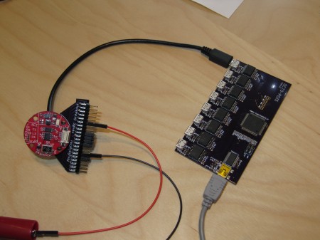
So far so good with the new boards.  I started very carefully by feeding it 5V on the intermediate rail to see if the 3.3v supply comes up, which it did.  Next was hotwiring the microcontroller to my AVR-ISP mkII and confirming the chip is happy, then replacing that with one of my program/debug boards and connecting it to my isolated 8-channel programmer:

I’m taking the old codebase and rebuilding it module-by-module so I can clean things up as I go, and make the main loop more configurable for various experiments.  After getting the serial port (which is running over the same cable, to my programming board) up and running, I moved on to the FD77T (which is an CDCE949 + crystal).  Now I’m starting to build in all the other subsystems necessary to get the thing actually talking to other units…